Skip to content Skip to sidebar Skip to footer

Flare System Design Basis

Manage Change To Flare Systems Aiche

Manage Change To Flare Systems Aiche

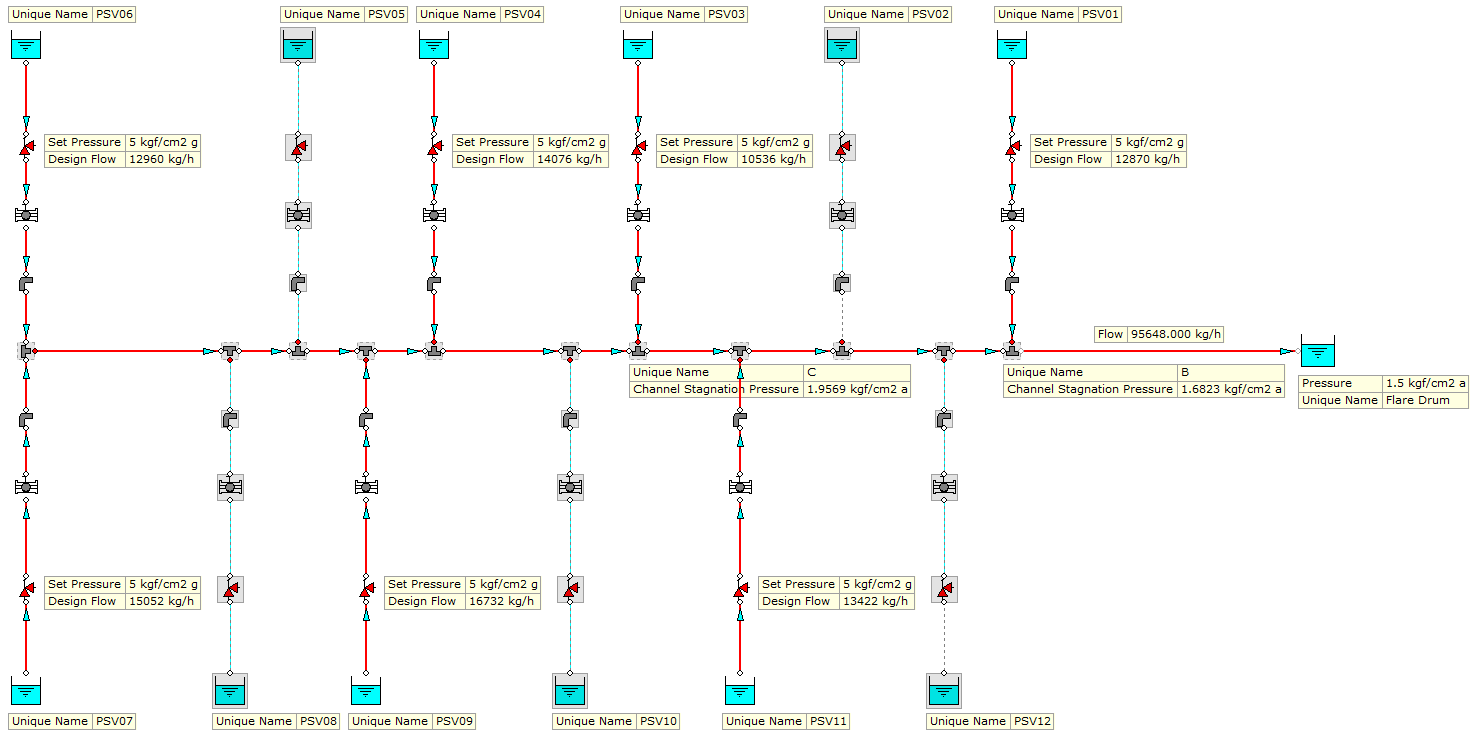
Flare system design basis. The relief loads in this case. In the event of major failure excess flow is automatically diverted by a seal to a second flare. Flare system or low pressure flare system depending upon the set point of pressure relief valves PRV and relief sources.

Criteria To Exclude Data Points 2-12 Table 3-1. Both high and low pressure gases can be handled in this combustion system. 51203 kgh 5 of design load for main flare 530.

The air assisted ground flare system is based on a center air assisted flare burner which ensures proper mixing of gas and air to give complete and smokeless combustion in a short vertical flame with low heat radiation. Since the possibility of a major failure is. Effective PRFS design helps companies meet risk management goals compliance requirements and sound business practices.

Regulatory design basis development included determination of the required flare organic destruction efficiency operating parameters and siting requirements. Experimental data provided support for EPAs. After filling this line with the mixture it is ignited by a spark.

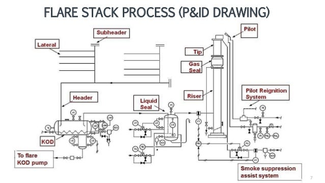
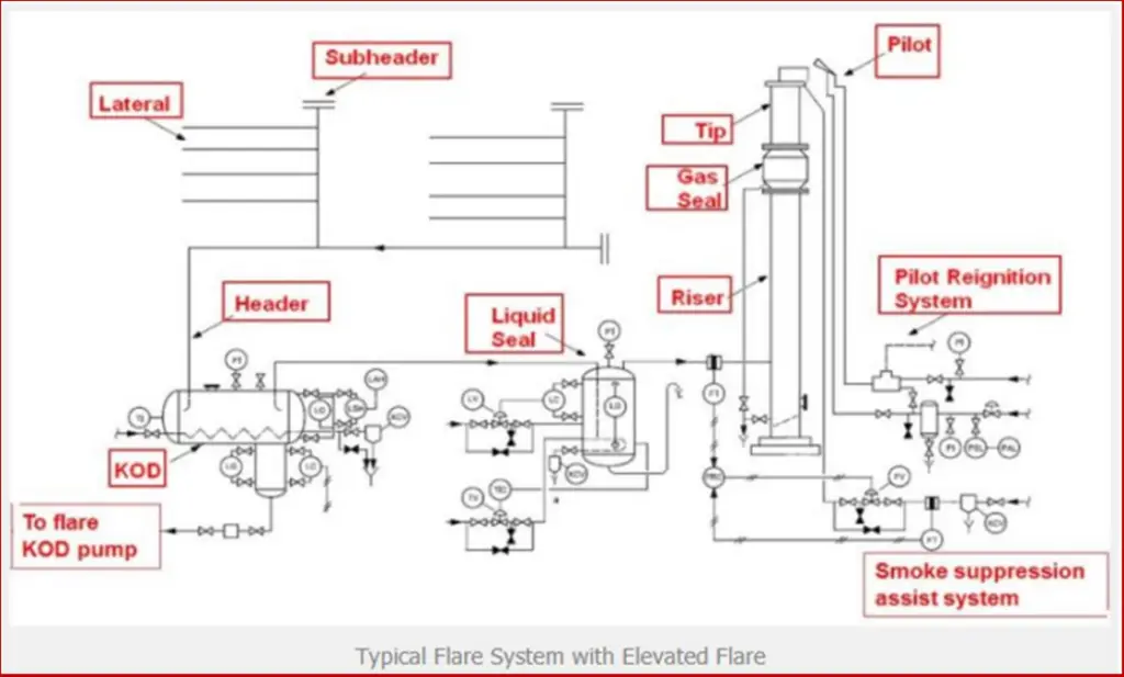
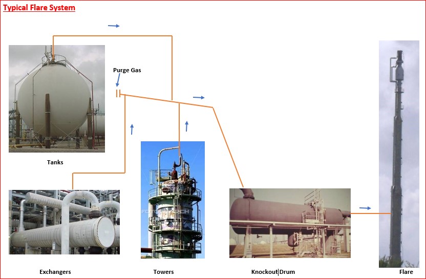
Maximum continuous-flare design is based on loss of produced-gas transport single compression shutdown gas-turbine shutdown etc. The flare and vent systems should be designed to safely dispose of relieving hydrocarbon fluids as may be required during start-up operational upsets emergency shutdown and maintenance activities. The flare and vent systems should be designed in accordance with.

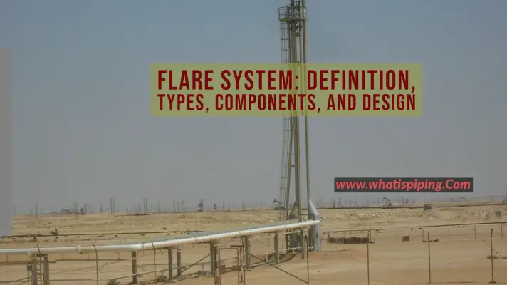
Here in the US that was most likely 35-45 years ago. A system of Process Safety Management PSM critical mechanical equipment that gathers and safely burns hydrocarbons from pressure-relieving and vapour depressurizing systems. Typical flare mountings on an offshore platform are angled boom mounting most common vertical towers or remote flare.

The vapor is effectively non-toxic and non-corrosive. For detailed relief loads in other cases refer to Study Report for Flare System T-FE-S330-1222-0001.

Flare System Definition Types Components And Design With Pdf What Is Piping

Flare System Definition Types Components And Design With Pdf What Is Piping

Gas Flare Stack Process

Gas Flare Stack Process

Precise Engineering Inc

Precise Engineering Inc

Flare System An Overview Sciencedirect Topics

Flare System An Overview Sciencedirect Topics

2

2

2

2

Basics Of Flare System In Any Operating Plant Design And Engineering

Basics Of Flare System In Any Operating Plant Design And Engineering

Manage Change To Flare Systems Aiche

Manage Change To Flare Systems Aiche

2

2

Flare System Types Segregation Tips Purge System And More

Flare System Types Segregation Tips Purge System And More

Flare System Definition Types Components And Design With Pdf What Is Piping

Flare System Definition Types Components And Design With Pdf What Is Piping

Flare System An Overview Sciencedirect Topics

Flare System An Overview Sciencedirect Topics

Process Engineer Built Up Back Pressure Calculation

Process Engineer Built Up Back Pressure Calculation

Design Basis For Flare System Pdf Valve Liquids

Design Basis For Flare System Pdf Valve Liquids

Flare System Modelling For Dummies Features The Chemical Engineer

Flare System Modelling For Dummies Features The Chemical Engineer

Schematic Diagram Of The Lab Scale Flare System Modular Burner Detail Download Scientific Diagram

Schematic Diagram Of The Lab Scale Flare System Modular Burner Detail Download Scientific Diagram

Design Basis For Flare System Pdf Valve Liquids

Design Basis For Flare System Pdf Valve Liquids

Basics Of Flare System In Any Operating Plant Design And Engineering

Basics Of Flare System In Any Operating Plant Design And Engineering

Gas Flare Stack Process

Gas Flare Stack Process

Design Philosophy For The Flare Vent Relief And Blowdown Systems

Design Philosophy For The Flare Vent Relief And Blowdown Systems

Relief Valve Sizing Fluidflow Fluidflow

Relief Valve Sizing Fluidflow Fluidflow

The Gas Flare Stack Process Grin

The Gas Flare Stack Process Grin

2

2

1

1

Gas Flare Stack Process

Gas Flare Stack Process

Flare Relief System Verification By Worleyparsons Issuu

Flare Relief System Verification By Worleyparsons Issuu

Flare System Design For A Refinery Mega Complex Front End And Beyond

Flare System Design For A Refinery Mega Complex Front End And Beyond

Cybosoft Releases Flare Control System Design Guide To Help Refineries Comply With Epa Rsr 63 670 Rules

Cybosoft Releases Flare Control System Design Guide To Help Refineries Comply With Epa Rsr 63 670 Rules

Flare System Modelling For Dummies Features The Chemical Engineer

Flare System Modelling For Dummies Features The Chemical Engineer

Flare System Types Segregation Tips Purge System And More

Flare System Types Segregation Tips Purge System And More

Pdf Improve Flare Management

Pdf Improve Flare Management

Flare System Design Basics Familiarization Module Pdf Natural Gas Chemical Process Engineering

Flare System Design Basics Familiarization Module Pdf Natural Gas Chemical Process Engineering

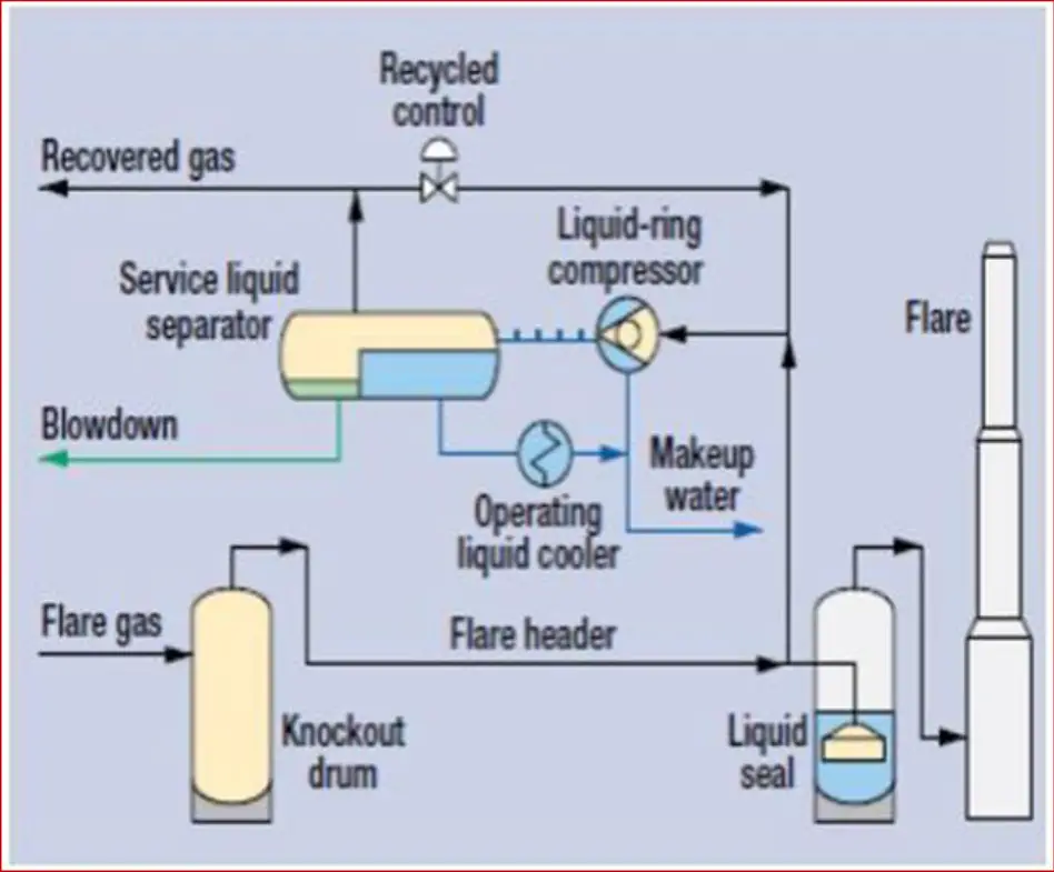
Optimize Flare Gas Recovery System Design To Reduce Emissions

Optimize Flare Gas Recovery System Design To Reduce Emissions

2

2

Overpressure Protection System Verification Oil Gas Sectors Process Systems Enterprise Process Systems Enterprise

Overpressure Protection System Verification Oil Gas Sectors Process Systems Enterprise Process Systems Enterprise

Flare Tip An Overview Sciencedirect Topics

Flare Tip An Overview Sciencedirect Topics

Flare System Definition Types Components And Design With Pdf What Is Piping

Flare System Definition Types Components And Design With Pdf What Is Piping

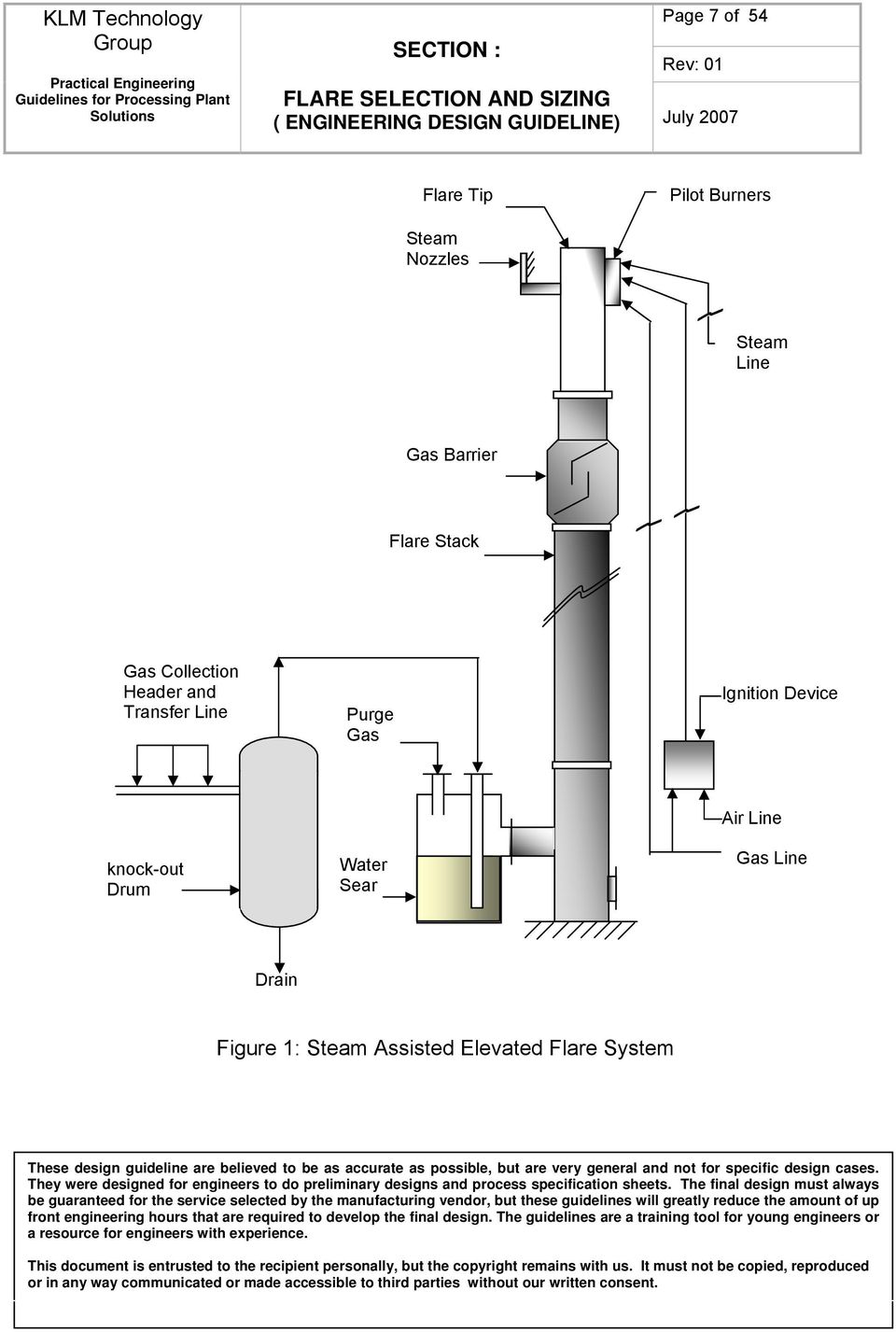
Flare Selection And Sizing Engineering Design Guideline Pdf Free Download

Flare Selection And Sizing Engineering Design Guideline Pdf Free Download

2

2

2

2

Flare System Types Segregation Tips Purge System And More

Flare System Types Segregation Tips Purge System And More

Total Flare System Design And Analysis

Total Flare System Design And Analysis

Flare System Modelling For Dummies Features The Chemical Engineer

Flare System Modelling For Dummies Features The Chemical Engineer

Process Design Manual Flare System

Process Design Manual Flare System

Flare Selection And Sizing Engineering Design Guideline Pdf Free Download

Flare Selection And Sizing Engineering Design Guideline Pdf Free Download

Schematic Diagram Of The Lab Scale Flare System Modular Burner Detail Download Scientific Diagram

Schematic Diagram Of The Lab Scale Flare System Modular Burner Detail Download Scientific Diagram

Iocl Flare Design Basis Refrigeration Hvac

Iocl Flare Design Basis Refrigeration Hvac

Flare System Definition Types Components And Design With Pdf What Is Piping

Flare System Definition Types Components And Design With Pdf What Is Piping

Https Encrypted Tbn0 Gstatic Com Images Q Tbn And9gcteyuzpvtgdjzb0spmkliagq6ckl9gk39dkuwgx3tanlbddeqny Usqp Cau

Https Encrypted Tbn0 Gstatic Com Images Q Tbn And9gcteyuzpvtgdjzb0spmkliagq6ckl9gk39dkuwgx3tanlbddeqny Usqp Cau

51203 kgh 5 of design load for main flare 530.

A system of Process Safety Management PSM critical mechanical equipment that gathers and safely burns hydrocarbons from pressure-relieving and vapour depressurizing systems. In general the high pressure flare system shall dispose of hydrocarbon releases from relief valves with a nominal set pressure of 95 kgcm2G and higher and the low pressure flare. Vapor which is lighter than air or vapor of any molecular mass that is non-flammable non-hazardous and non-condensable. Must be continuously available. Odds are that it was part of the original design of the facility. System has multiple flares to treat the various sources for waste gases. The flare and vent systems should be designed in accordance with. Flare system or low pressure flare system depending upon the set point of pressure relief valves PRV and relief sources. Typical flare mountings on an offshore platform are angled boom mounting most common vertical towers or remote flare.


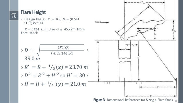
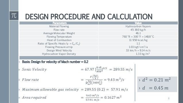
Technical Basis for Flare Parameters Where. In general the high pressure flare system shall dispose of hydrocarbon releases from relief valves with a nominal set pressure of 95 kgcm2G and higher and the low pressure flare. The PFD depicted process unit operations and mass and energy balance information for the process vent streams. Maximum emergency-flare design is based on emergency shut in of the production manifold and quick depressurization of the system. Vapor which is lighter than air or vapor of any molecular mass that is non-flammable non-hazardous and non-condensable. Effective PRFS design helps companies meet risk management goals compliance requirements and sound business practices. Technical Basis for Flare Parameters Where.

Post a Comment for "Flare System Design Basis"